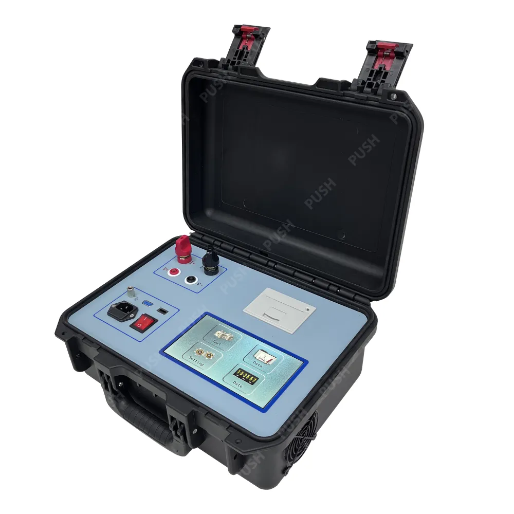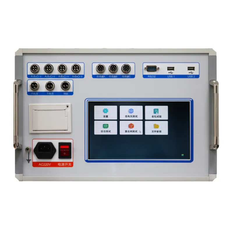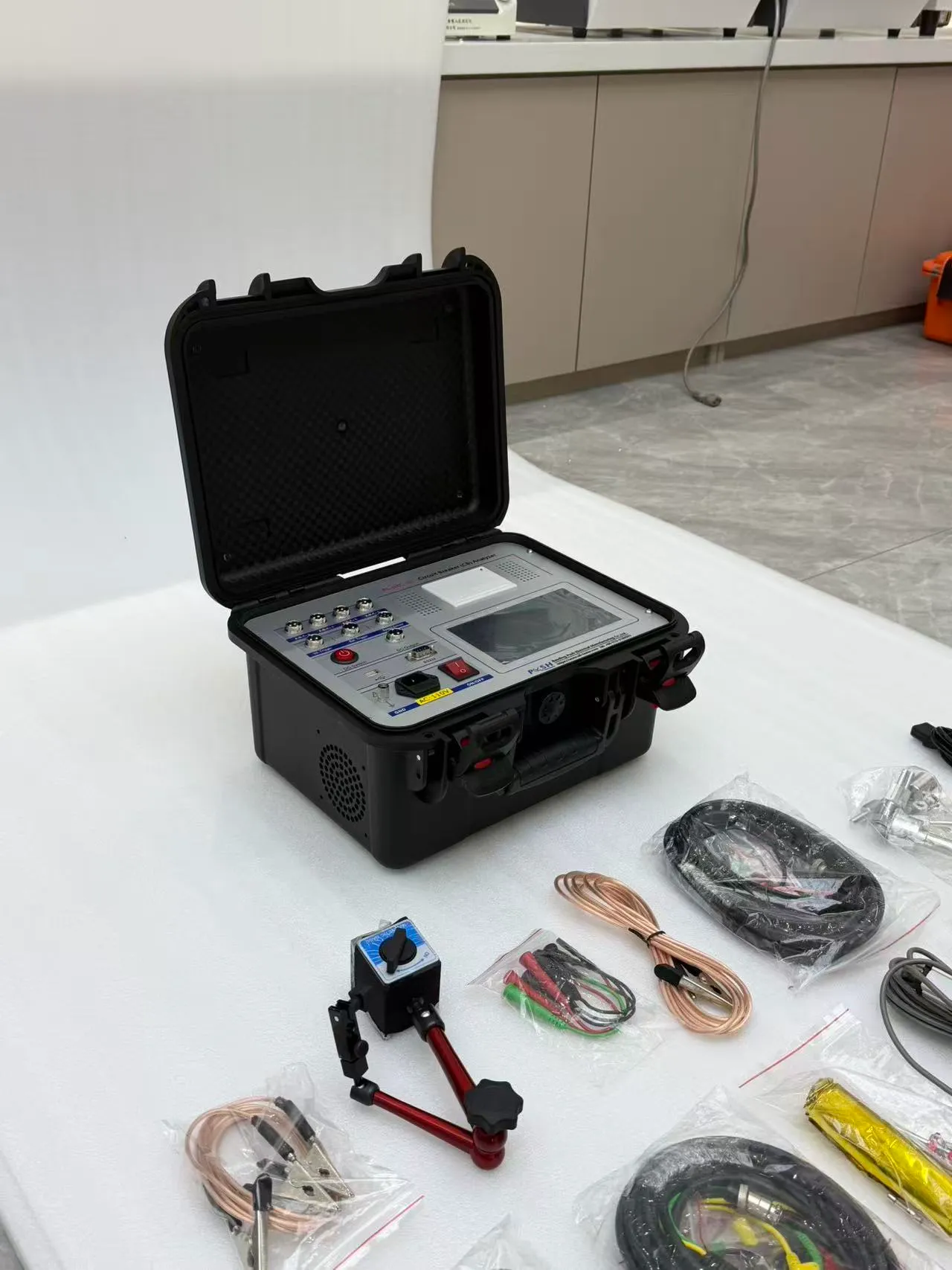
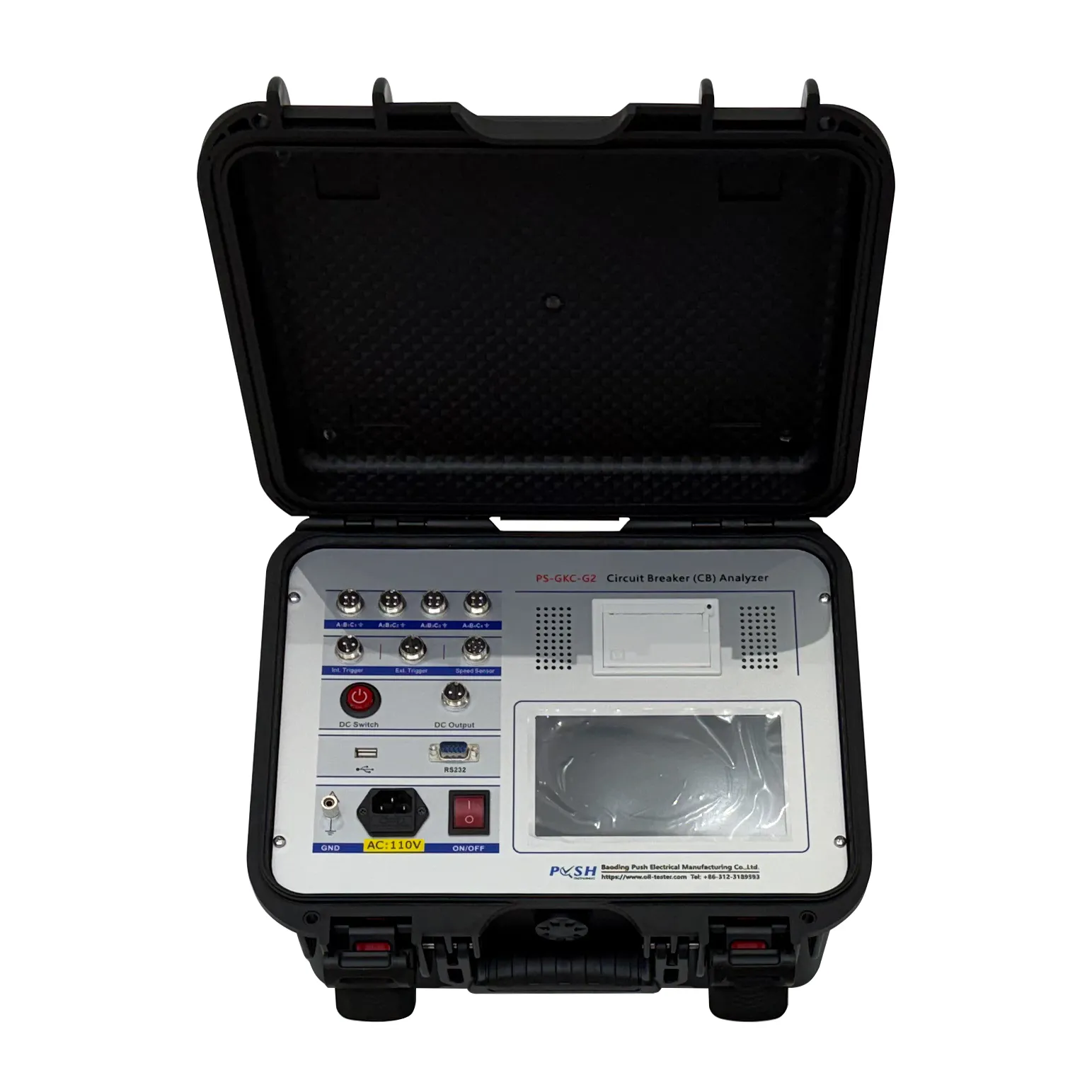
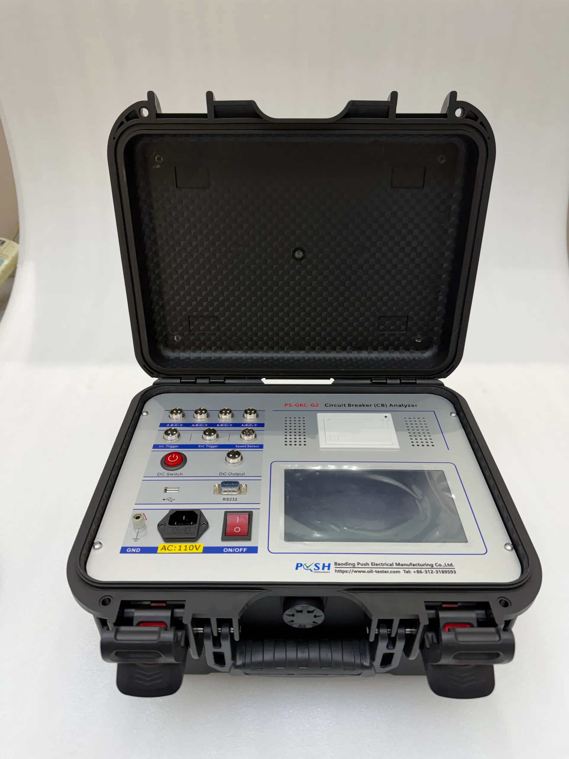
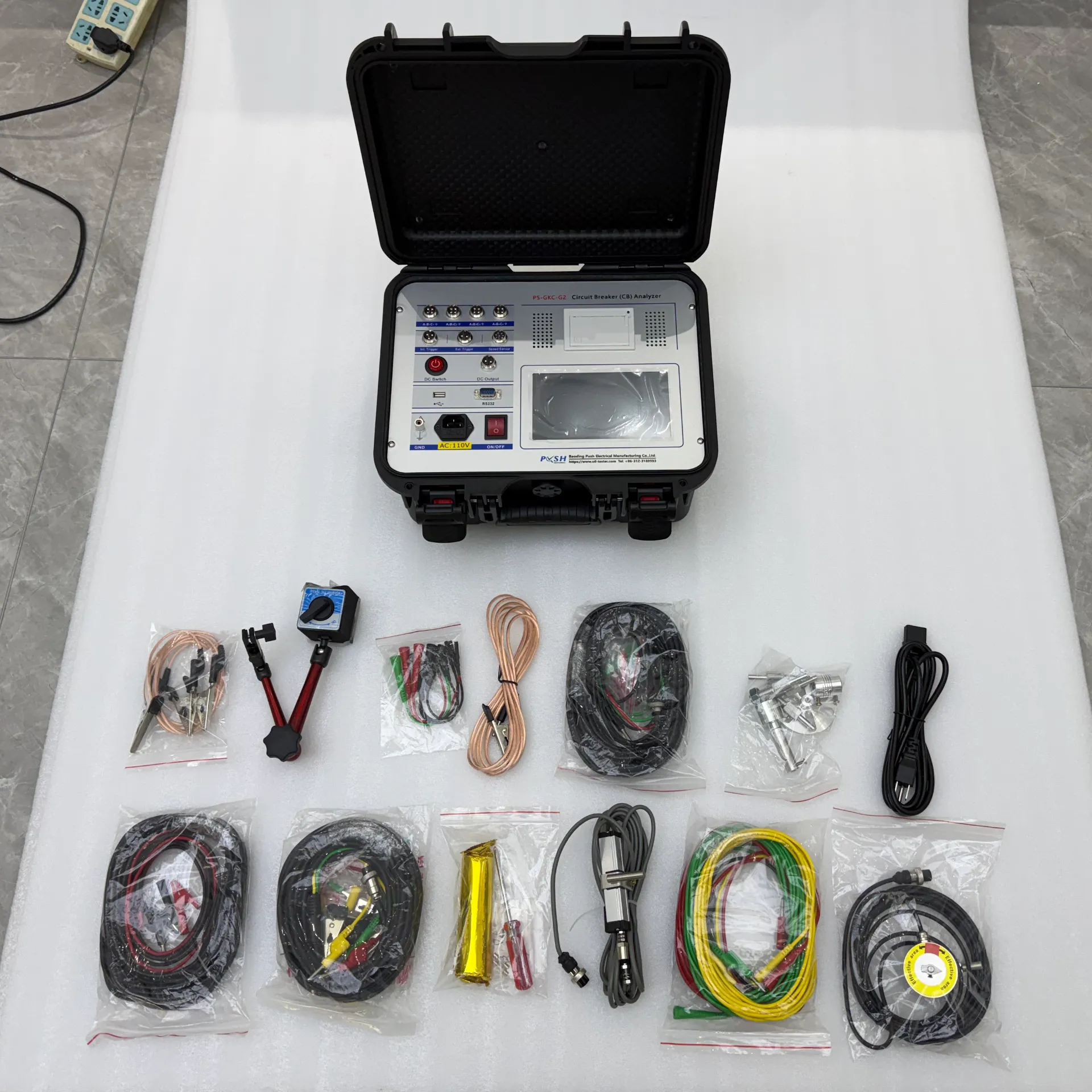
Portable switch characteristic tester
Applicable to SF6 switches, GIS switchgear, vacuum switches, oil switches, and vacuum contactors (electrically held single coil; for double coil contactors, select the vacuum switch type). It can simultaneously measure 12 channels of metal contact breaks, 6 channels of main breaks, and 6 channels of auxiliary breaks.
- Categories:HV Switch Tester
Applicable to SF6 switches, GIS switchgear, vacuum switches, oil switches, and vacuum contactors (electrically held single coil; for double coil contactors, select the vacuum switch type). It can simultaneously measure 12 channels of metal contact breaks, 6 channels of main breaks, and 6 channels of auxiliary breaks.
Features
(1) The integrated internal operating power supply eliminates the need for a separate on-site power supply, enabling quick and convenient operation. It provides a continuously adjustable DC power output of 20–270 V with a maximum instantaneous current of 30 A. The unique dual-circuit power-supply design also allows closing and opening circuit testing even if one circuit fails.
(2) The unit is equipped with a linear sensor and a rotary sensor, along with dedicated fixed multi-functional connectors, making installation fast and straightforward. The linear sensor length can be set arbitrarily from 30 to 1000 mm. Once the sensor is installed, the instrument does not require factory reprogramming.
(3) The main unit can store up to 100 sets of current test data, and includes an internal real-time clock for convenient data archiving.
(4) Equipped with a USB flash drive interface and an RS232 interface. Test data can be saved to a USB flash drive and uploaded to a computer for analysis, storage, and printing. The RS232 interface supports online computer connection (optional).
(5) Internal anti-interference circuitry ensures reliable operation in 500 kV substations.
Technical parameters
|
1. Time measurement |
12-channel inherent opening (closing) time |
|
Asynchrony within opening (closing) phases |
|
|
Difference in asynchrony between opening (closing) phases (1–99 ms) |
|
|
Closing (opening) bounce time (number of bounces) |
|
|
Internal trigger test range: 1 ms–10,000 ms; resolution: 0.01 ms |
|
|
External trigger test range: 1 ms–10,000 ms |
|
|
Resolution: within 999 ms: 0.01 ms; 1,000–9,999 ms: 0.1 ms; above 10,000 ms: 1 ms |
|
|
Accuracy within 200 ms: 0.05% ± 0.1 ms |
|
|
2. Speed measurement |
Speed at initial separation (or engagement) Average speed over a specified time period (stroke or angle segment) |
|
3. Measurement range |
Linear sensor: 0.01–20.00 m/s; accuracy ±0.1 m/s |
|
345° angle sensor: 0.01–20.00 m/s; accuracy ±0.1 m/s |
|
|
4. Stroke measurement |
Moving contact stroke (stroke) |
|
Contact stroke (opening distance) |
|
|
Overtravel |
|
|
Overshoot or rebound stroke |
|
|
5. Measurement range |
Linear sensor: 50 mm; measurement range: 0–50 mm; resolution 0.1 mm. Optional linear sensor of any length from 100–1000 mm. |
|
Rotary sensor: 345° rotary sensor; measurement range: 0–1000 mm; resolution 0.08°. Accuracy ±(1%L + 0.2) mm |
|
|
6. Current and resistance range |
Maximum current: 20 A; resolution: 0.01 A. Resistance: 1000 Ω; resolution: 0.01 Ω. Accuracy ±5% |
|
7. Instrument power supply |
AC 220 V ±10%; 50 Hz ±10% |
|
8. DC power output |
DC 20–270 V continuously adjustable; maximum instantaneous current: 30 A; power: 3300 W |
|
9. External trigger voltage |
AC/DC 10–300 V; current ≤120 A |
|
10. Measurement range of disconnecting switch or energy storage circuit breaker |
(1) Voltage output: DC 20–270 V (adjustable) |
|
(2) Power output time: 0.01–10 seconds (adjustable) |
|
|
(3) Maximum acquisition time of disconnection signal: 10 seconds |
|
|
(4) Measurable disconnection closing/opening time, three-phase asynchrony, bounce time, and bounce count |
|
|
11. Main unit dimensions |
360 × 260 × 170 mm |
|
12. Operating environment |
-20°C to +50°C |
|
13. Relative humidity |
≤ 90% |